|
|
Post by Bob on Jun 12, 2011 14:15:20 GMT -5
Hi Steve,
I suggest some experiments to try to pin down why there is a difference in the results:
1. Measure each piece of coax open circuited using the "Distance to Fault" function. That will show you the nominal impedance, Zo, at the one-eight wave frequency.
2. Terminate each piece of coax with 50 ohms and do a regular impedance scan from 1 to 20 MHz. Note what the SWR is. This should correspond pretty closely to the Zo values from step 1.
3. Test each piece of coax with a 50 ohm termination in the TDR mode.
4. Cascade them two pieces at a time and check with the TDR with the cable open and with it terminated in 50 ohms.
5. Test all three pieces with them terminated in 50 ohms.
When several cables are involved, there is the possibility for reflection at each joint. The reflection at each discontinuity affects the signal traveling in both directions. These multiple reflections can complicate the display.
--73/Bob
|
|
g3txq
New Member

Posts: 34
|
Post by g3txq on Jun 15, 2011 4:50:04 GMT -5
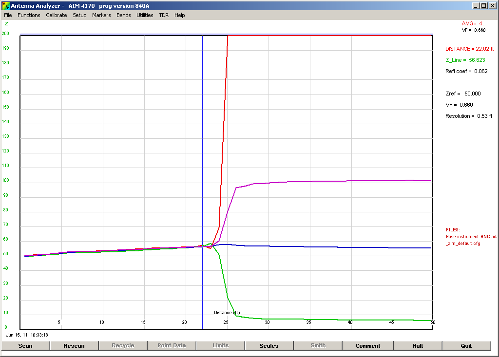
Bob, Here's a much more straightforward example of what I am talking about:  This is a single, continuous, 24ft length of RG174 terminated in an Open Circuit (Red), a Short Circuit (Green), a 50 Ohm load (Blue) and a 100 Ohm load (Mauve). What is puzzling me is the steady change in impedance along the length of RG174 in all cases from 50 Ohms to nearly 57 Ohms. 73, Steve G3TXQ |
|
g3txq
New Member

Posts: 34
|
Post by g3txq on Jun 15, 2011 6:25:13 GMT -5
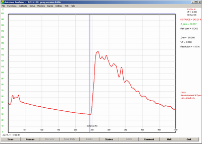
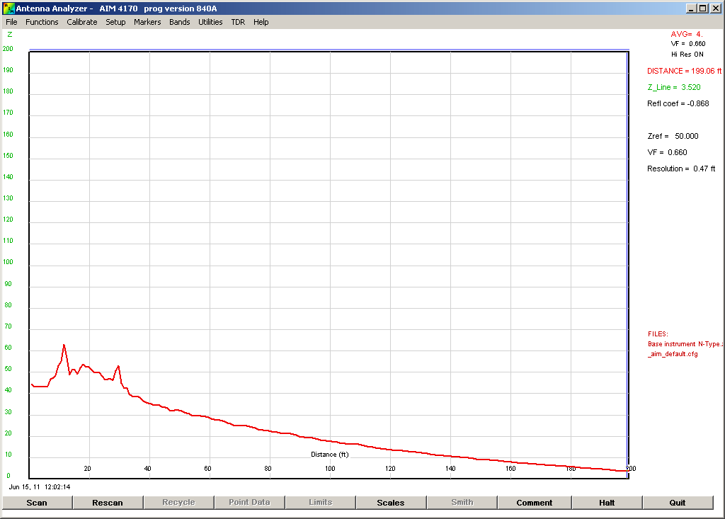
Here are the scans which originally got me wondering:  This is a 240ft run of RG213 to my hexbeam. The hexbeam perturbation at 240ft is clear, as are the reflections close to the shack where I'm running through various coax switches and other station equipment. The AIM reports a steady impedance drop along the RG213 from 50 Ohms to 30 Ohms. If I simply change the distance scale to 200ft and re-scan, I get something even odder:  The impedance along the RG213 now drops from 50 Ohms at the shack to nearly zero at 200ft 73, Steve G3TXQ |
|
g3txq
New Member

Posts: 34
|
Post by g3txq on Jun 15, 2011 10:45:26 GMT -5
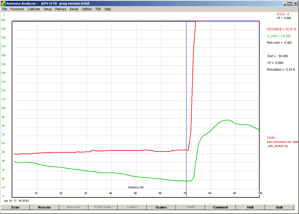
Bob, One final chart, then I promise not to trouble you further:  The green trace is a 5-band (20m thru 10m) fan dipole fed through 70ft of RG58 coax. The red trace is the same cable with the antenna disconnected at the feedpoint. With the antenna connected the impedance of the RG58 appears to fall steadily from 40 Ohms to 18 Ohms. With just an Open Circuit it's fairly steady at 50 Ohms. 73, Steve G3TXQ |
|
|
|
Post by Bob on Jun 16, 2011 21:37:03 GMT -5
The upward slope of Z seems to be caused by loss in the cable. I simulated this with a program to compare the results with and without loss. The impedance as a function of frequency varies a lot when loss is included in the calculations. Thanks to Dan, AC6LA, for his very interesting work on transmission line modeling.  No Loss
 With Loss corresponding to RG174 -- 73/Bob |
|
g3txq
New Member

Posts: 34
|
Post by g3txq on Jun 17, 2011 9:02:53 GMT -5
Bob, Thanks for that. But I guess it leads to further questions: 1) Why does the impedance fall with distance when an antenna is connected to the feedline, but not when the feedline is Open Circuit? 2) Why does the impedance of the RG174 increase with distance by exactly the same amount no matter whether it is terminated in 50 Ohms , left Open Circuit, or made Short circuit? The cable loss would be very different in those three cases; I would have expected that if the impedance variation with distance depended on cable loss it would be different depending on the termination! 2) I would have thought that increasing cable loss would have established the impedance closer to Zo, not moved it away; that's what happens with normal impedance measurements - I'm not clear why a TDR impedance measurement would be different? Bob, please don't think I'm being "difficult" - I'm genuinely trying to understand  73, Steve G3TXQ |
|
|
|
Post by Bob on Jun 17, 2011 10:02:17 GMT -5
The loss of the cable is a physical property of the cable, so it is not affected by the termination. The overall response in the time domain gets very complicated when multiple reflections are involved, so it's hard to visualize what the response will be. The TDR is a handy tool for some situations but in many cases, the frequency domain is better. It's sort of like the difference between a scope and a spectrum analyzer. Here's a picture showing the cable with a 50 ohm termination:  --73/Bob |
|
g3txq
New Member

Posts: 34
|
Post by g3txq on Jun 17, 2011 10:20:34 GMT -5
Bob, Understood! My interest in this was sparked when I looked at the new TDR material in Ian's (G3NRW) revised PowerPoint presentation. I was sceptical about his conclusion that the variation in the open-wire Zo reported by the AIM is due to proximity to the ground and other objects; that may account for some of it, but not all I believe. It would be interesting to see a comparison TDR scan with the doublet disconnected. I see tremendous value in the TDR mode for locating the position of perturbations etc; but for now I'll proceed with caution where impedance measurements are concerned  Thanks for taking the time to respond, and thanks for a great product! 73, Steve G3TXQ |
|
k9fv
New Member

Posts: 37
|
Post by k9fv on Jun 18, 2011 7:58:39 GMT -5
A very good discussion - This has helped me understand some of the questions I had when playing with the TDR function. I LOVE my AIM4170 and wouldn't give it up for anything...... except maybe the UHF version:)
I am SO GLAD ya'll had this on the forum rather than private emails.
73 de Ken H>
|
|
mac
New Member

Posts: 13
|
Post by mac on Jul 21, 2011 22:32:46 GMT -5
Bob and I have discussed the unexpected results of using the TDR function on long pieces of cable. I just have not returned to this forum is some weeks.
Using the TDR function on long Heliax runs gives results that are just unexpected. However, the TDR function does seem to produce reasonable results out to 100 feet - maybe 200 feet - but I urge caution in using results from longer TLs. Perhaps a different sample spacing is needed.
The AIM4170C is invaluable for measuring Z and crystals. I would not wish to be without the instrument. For under 1k one can do so much more with so much more ease than using GR bridge, oscillator, and receiver. 73 Mac N8TT 11:33 P.M.
|
|